I built this scooter for my two of my three boys, after several years
of part time tinkering and several failures with a Poulan Weedeater and other
failures I am happy to submit info and pictures of my final fun project, which is the envy of the neighborhood.
It cruises at between 15 and 20 miles per hour and is much different to most of the other scooters I've seen
on your website.
It is a belt drive, running a 3 speed hub that has been grafted into a nylon wheel.
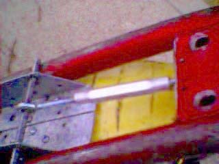
I haven't done anything to the clutch except put a real thin washer behind it and lubed the side next to the motor so the belt isnt cut up.
The teeth on the clutch are not very pointed and I believe there are five of them.
The belt fits snugly between the back of the clutch and the washer up against the motor.
I really don't know if the bottom of the v groove actually touches the teeth, more like gripping the side of the v groove and the washer.
I am still on the original belt, but have noticed some wear and rubber dust behind the clutch.
When it wears out I'll go buy another $3 belt
As you can see I turned the platform up-side down by inverting the frame on the gooseneck and
removing the platform. It is a standard 12" older style Magna brand push scooter, made in the R.O.C.
I added BMX type pegs on the rear axle which the boys stand on.
The scooter is belt driven by a Skilsaw 1616 chain-saw motor.
(Out of business over 20 years ago and discontinued) Parts? What parts! The chainsaw was given to me, what can I say?
The motor is mounted upside-down and out of the way under the hump in the middle to get the
counter clock-wise rotation needed, otherwise it would want to go backwards. It is secured by two
wood joist hanger brackets screwed to the bottom of the motor and a rod through the top end
crossing over the top of the frame. Belt tension is adjusted by a turn-buckle between two eye-bolts,
one through the rod and the other through frame of the scooter.
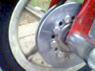
The rear wheel hub was milled out to accomodate a three speed hub from a J.C. Penney bicycle.
The spokes were removed from the 3-speed axle and the ring with the holes for the spokes was cut
flush with the hub. The hub, with the sprocket still on the other side was inserted into the milled out axle
and bonded with plastic/steel epoxy and balanced. The sprocket has eighteen teeth and a rod that is
pulled to change gears internally in the axle. A 5" diameter pully is mounted to the sprocket. A 2"
diameter hole was cut in the center of the pulley and (18) 3/8" holes were drilled 20 degrees apart to
mount exactly where the chain links fit over the sprocket.
(9) 3/8" bolts with lock washers secure every other hole because one in each hole wouldn't fit.
The welded rear brake support and brakes were removed so I could stretch the frame at the wheel so the wider 3-speed hub and sprocket would fit.
I haven't replaced the brake and frame support yet, so I now only have front brakes.
I have already gone through one set of front pads, but rear brakes will be added again later.
The belt at the motor fits behind the clutch where the chain goes with no other modifaction other than a thin washer next to the motor.
Having a pully built into the clutch would be nice though.
One disavantage is that the gears cannot be changed on the fly because the cable sticks out and
can entangle your feet. They however can be changed by adjusting the screw and nut sticking out of the
peg for different gears and weight of riders..